"Form 4b" appears on many switchboard specifications because it sounds like the safest choice. Sometimes it is the right choice. Often a Form 2 or Form 3b board would do the same job in less space, for less money and with less heat to manage. This guide explains what each form of internal separation does under IEC 61439-2, and how to pick the right one.
What internal separation is for
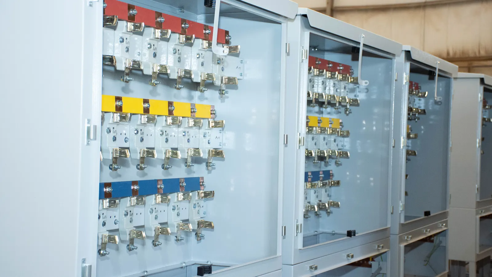
A switchboard has three kinds of parts that may need to be kept apart: the busbars, the functional units (an incomer, a feeder breaker, a motor starter) and the terminals for external conductors, where the site cables land. Internal separation uses barriers or partitions to divide them.
The standard gives separation two jobs: protection against contact with live parts of a neighbouring unit (at least IPXXB, finger-safe) and protection against solid foreign objects passing from one unit to another (at least IP2X). In short, it lets a person work on one part of a board while other parts stay live, more safely.
One point is often misunderstood: forms of separation are not an internal arc rating. Containment of an arcing fault is assessed separately, under IEC/TR 61641. If arc protection matters on your project, specify it separately.
The four forms
| Form | Busbars separated from units | Units separated from each other | Terminals separated from units | Terminals separated from busbars |
|---|---|---|---|---|
| Form 1 | No | No | No | No |
| Form 2a | Yes | No | No | No |
| Form 2b | Yes | No | No | Yes |
| Form 3a | Yes | Yes | Yes | No |
| Form 3b | Yes | Yes | Yes | Yes |
| Form 4a | Yes | Yes | Yes, terminals in the same compartment as their own unit | Yes |
| Form 4b | Yes | Yes | Yes, terminals in their own compartment | Yes |
Form 1
No internal separation. To work inside, the whole board is switched off. Fine for small boards where a shutdown is acceptable.
Form 2
The busbars are behind a barrier, but the functional units share one space. In 2b the cable terminals are also kept away from the busbars, so cables can be connected with less risk of touching the main bars.
Form 3
Each functional unit has its own compartment, so one feeder can be isolated and worked on while the others run. In Form 3 the terminals of all units share a cable zone; in 3b that zone is separated from the busbars. Form 3b is a common choice for industrial boards.
Form 4
As Form 3, and the terminals of each unit are separated from the terminals of every other unit. In 4a each unit's terminals sit inside that unit's compartment; in 4b they sit in a separate compartment of their own. Form 4 allows cable work on one feeder while the neighbouring feeders stay in service.
BS EN 61439-2 Types 1 to 7
The British edition of the standard adds a national annex that describes Form 4 more precisely, as Types 1 to 7. The types say how separation is made, with insulated coverings (sleeving, shrouds) or with rigid metal or insulating barriers, and where the cable terminals sit. Type 7 is the most complete, with rigid barriers and the terminals of each unit in their own compartment. Specifications from the UK, the Gulf and many African markets that follow British practice often ask for "Form 4 Type 7" on main boards.
How to choose
| Situation | Usual choice |
|---|---|
| Small sub-board, shutdown for maintenance is acceptable | Form 1 or 2 |
| Commercial building sub-main board | Form 2b or 3b |
| Industrial main board, feeders serviced one by one | Form 3b or 4a |
| Hospital, data centre, airport, process plant: no shutdown allowed | Form 4b, with withdrawable units where needed |
| Motor control centre with frequent changes | Form 4 with withdrawable or plug-in units |
Higher forms cost more. Each barrier takes space, so cubicles get wider or deeper, and a more enclosed board dissipates heat less well, which can mean derating in a hot plant room. Choose the form from how the board will be operated and maintained, not from the highest number available. Write the maintenance rule into the specification: "feeders must be isolated and worked on while adjacent feeders remain energised" says more than "Form 4b" alone.
Forms of separation at SEGA M
SEGA M builds SIVACON S8 switchboards in Egypt as a Siemens Advanced Partner. The system covers Form 1 to Form 4 under IEC 61439-2, and up to Form 4 Type 7 under BS EN 61439-2, with circuit-breaker, universal mounting, fixed-mounted and in-line designs. For main distribution with our own design, see the SEGA M SG-1 switchgear.
Not sure which form your project needs? Send us the single-line diagram and tell us how the board will be maintained. Our engineers will propose a form and a layout, and explain the cost and size difference between the options.
Frequently asked questions
Is Form 4b always safer than Form 3b?
It gives more separation at the cable terminals, which matters when cables are worked on with neighbouring feeders live. If your site never does that, Form 3b may be enough.
Does a higher form protect against arc faults?
Not by itself. Internal arc behaviour is assessed separately under IEC/TR 61641.
What does "Form 4 Type 7" mean?
It comes from the British national annex of BS EN 61439-2. Type 7 uses rigid barriers and gives each unit's cable terminals their own compartment.
Which forms does SEGA M build?
SIVACON S8 boards built by SEGA M cover Form 1 to Form 4, and up to Form 4 Type 7 under BS EN 61439-2.